

Autogeen Lassen:
- Materialen worden samengevoegd zonder de toevoeging van extra materialen, wat het hoogste niveau van fixatie en voegvoorbereiding vereist. Aangezien er geen materiaal wordt toegevoegd, is het noodzakelijk dat de te lassen materialen in nauw contact blijven tijdens het lasproces. Elke significante scheiding van de materialen kan resulteren in een onaanvaardbaar lasprofiel of volledig falen van de lasverbinding. Wobble-3 voorkomen dat dit gebeurt!
- Voorbereiding om een consistente pasvorm van de lasnaad te garanderen, is een van de sleutels tot succesvol fiberlaserlassen. Een belangrijk voordeel van fiberlaser zijn lasverbindingen met een uitzonderlijke cosmetische afwerking. In sommige gevallen zijn deze lasnaden bijna perfect vermengd met het omringende materiaal. Afhankelijk van de opspanning en de montage van de verbinding, kunnen sommige lassen een kleine concaafheid hebben (wat misschien niet acceptabel is voor productontwerpen die vermoeiingseigenschappen vereisen die vergelijkbaar zijn met die van het basismateriaal) of convexiteit. Wederom Wobble-3 vermijd deze problemen!

Additief Lassen:
Materiaal wordt meestal in de vorm van metaaldraad of poeder aan de lasnaad toegevoegd.
Drie redenen om materiaal aan de las toe te voegen zijn:
- Lasnaad: door extra materiaal toe te voegen, wordt de lasnaad toleranter voor uitlijnfouten. Aanvaardbare lassen kunnen worden geproduceerd uit verbindingen met een minder dan perfecte pasvorm.
- Lasgeometrie: toevoeging van vulmetaal wordt gebruikt om de vorm en grootte van de las te regelen. Door een kroon (convex oppervlak van de las) op de lasnaad te behouden, ontstaat er een versterking die belangrijk is voor verbindingen die mechanische sterkte en levensduur vereisen in de ontwerpprestaties van het product.
- Ongelijksoortige metalen: Vulmetaal wordt toegevoegd om het lassen van ongelijke metalen en legeringen te vergemakkelijken die anders metallurgisch incompatibel zijn.

Why Use Filler Metal with Laser Welding?
Applications for which filler wire is added during laser welding include:
- Improve the joint fit-up tolerance (air gaps, mismatch, etc.) of the parts to be welded.
- Eliminate solidification cracking during welding. For some aluminum alloys wire is used to replace the low melting temperature alloys and reduce the freezing point during cooling. For welding 6XXX series aluminum alloys, high silicon content wire such as 4043 or 4047 leads to reduced cracking and improved mechanical properties of these weld.
- Modify the chemical composition or the microstructure of the weld metal to obtain suitable mechanical properties.
- Improve the weld profile such as to avoid undercut at the top and bottom bead. Excessive undercut can act as stress raiser, which can reduce the mechanical properties of the weld during the service.
Laser welding with filler wire is a multi-parameter process.
Several laser and filler wire parameters influence weld quality.
Welding and filler wire speed:
The wire feed rate for a given weld joint gap and plate thickness is an important parameter and depends on welding speed, the cross sectional area of the gap between the joint face, and cross sectional area of the filler wire.
The relationship between welding speed and filler wire infeed is expressed as follows:
- Use of filler wire generally results in a 10% to 20% decrease in welding speed, for a given laser power, to compensate for the laser energy required to melt the wire.
- If the filler wire feed rate is too low, the amount of heat generated from the laser beam will affect the wire and the material being welded may be able to melt a bigger section of the wire end. This may result in breaking a liquid metal bridge formed during the process, the formation of a drop at the end of the wire, and momentary disturbance of the process stability.
- Too high filler wire feed rate causes the energy supplied to the welding area to be insufficient for stable and permanent wire melting. The volume of liquid metal at the end of the wire and in the liquid metal bridge increases thus flooding the air gap. Additionally, non-melted wire enters the back area of the pool, pushing out the liquid metal, which, by solidifying, forms characteristic humps of the weld surface and porosity at the root of the weld. Excessive wire speed can also reduce the penetration depth, weld width, and top bead height.
How to Determine Optimum Welding and Wire Speeds in Wire Feed Laser Welding ?
Laser beam – filler wire interaction:
An exposed length of wire that is too short prevents the wire from being melted at the initial area of the bead, and the laser beam directly affects the material to be melted. In turn, an exposed length of wire that is too long causes the extended wire end to be pressed against the plate surface, and as a result, at the initial stage, the laser beam melts the wire through, dividing it into two parts. In consequence, the spot at which the process starts is covered with a wire end welded onto the surface that is difficult to remove. In an extreme case, the welded-on wire end could cause a collision with the gas shielding nozzle, disturbing or even eliminating the gas shielding.
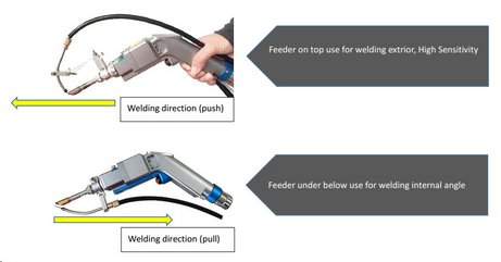
Wire feed delivery angle:
Angles between 30 and 60 degrees from the vertical can be used and 45 degree tends to be typical, as it simplifies setting the required wire intersection position with laser beam centerline. Angles greater than 60 degrees makes the latter difficult and angles less than 30 degrees causes the wire to intersect a large area of the laser beam, causing melting and vaporization of the wire without incorporating the metal into the weld pool.
Focused spot size:
The spot size should be close to the filler wire diameter. A laser spot size that is too small compared to the wire diameter can lead to welds with porosity because the filler wire has not melted properly.